
Gas Control
Showing a hierarchical system of state machines using the Gas example taken from our User Manual. It has been modified for the purpose of this case study.
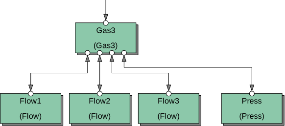
The example is of a control system to control gas inlets of a vacuum chamber used by semiconductor manufacturers (the figure below shows the control elements). The system contains flow control and pressure control elements. Three flow regulators supply three different gases to the chamber, and they are controlled by Flow state machines. The chamber is used for a manufacturing process that requires a certain vacuum in the chamber. The low pressure in the chamber is produced by vacuum pumps, not shown in the diagram. Effectively, the vacuum in the chamber is determined by the pumps and the gas flow. The pressure is continuously monitored, and if it exceeds the required range, the process is interrupted and the gas flow must be discontinued.

The system as designed contains 5 state machines: three Flow state machines for gas flow control, the Press state machine to monitor the vacuum in the chamber, and a Gas state machine that is a Master which coordinates the activities of the Flow and Press state machines.
Flow Control
Section titled “Flow Control”A gas flow regulator regulates the amount of gas passing through the gas inlet. The Flow state machine sets the required value of gas flow and monitors the true value of the flow. It is a kind of supervisor of the gas flow regulator. The gas flow regulator is a PID regulator and corrects the fast flow deviation. The Flow control reacts to permanent flow deviations which cannot be corrected by the gas flow regulator, issuing alarms and closing the flow in emergency cases.
The Flow state machine accepts commands (numbers) and sets an analog signal Flow_Ao (set value for the gas flow regulator) and a digital signal Flow_Do (open/close valve). As feedback from the attenuator, the state machine receives the actual gas flow value as an analog signal Flow_Ai. A switchpoint (SwipF) derives everything it needs to know from this single analog value: whether the valve has actually opened and whether the flow is within, above, or below the required range. Three commands determine regulator operations:
- Open the gas flow by setting the
Highvalue of the digital outputFlow_Do. - Close the gas flow by setting the
Lowvalue of the digital outputFlow_Do. - Set the gas flow to the value determined by the numerical output
Flow_Ao.
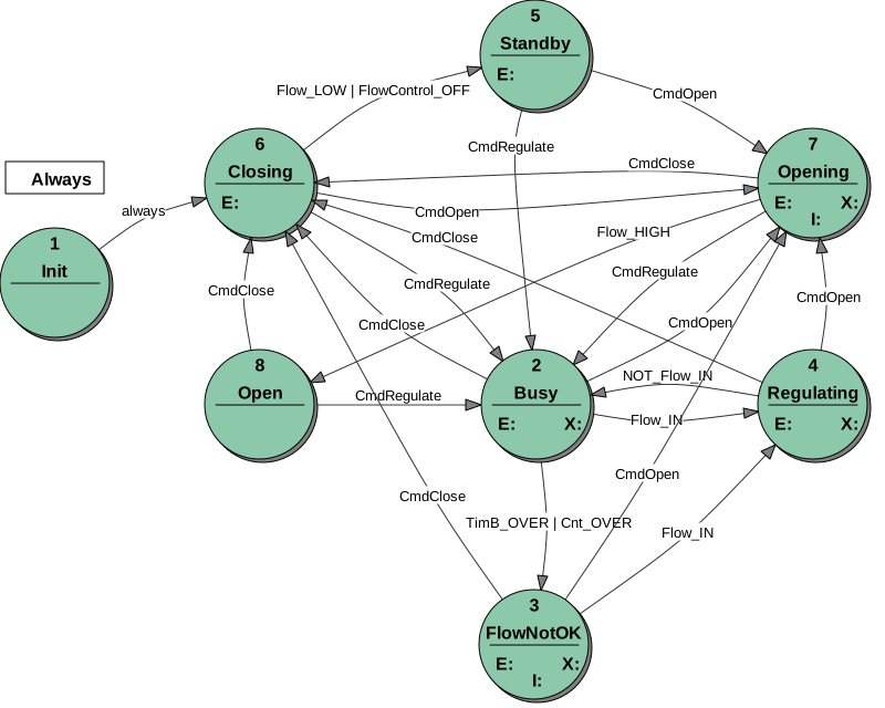
If the command Open has been carried out, the state machine should check whether the gas valve has been opened. If the valve does not open after a certain time, an alarm should be issued.
If the command Regulate has been carried out, the state machine should check whether the gas flow has reached the required value. If the flow cannot reach the value within a certain time, an alarm should be issued.
The actual gas flow is measured, and its value is delivered as an analog input signal Flow_Ai to the control system. Normally, it is required that the flow value stays within a certain limit. If the flow value exceeds the required range, the state machine should, after some delay, issue an alarm and count this event. If it happens more than a certain number of times, the state machine should issue the alarm immediately if the flow value exceeds the range.
You can find the details of the Flow state machine in its specification, especially in the state transition table. We show here only the state transition diagram, which gives a general impression of the Flow control.
Note that the Flow state machine has two Do outputs. The DoValve output is a control-relevant output used to open/close the gas flow valve. The DoRegulating output is only for the purpose of this case study, to show in SWLab that the gas flow value has reached the required value (i.e. the Flow state machine is in the state Regulating).
Pressure Monitoring
Section titled “Pressure Monitoring”The Press state machine does not perform any true control — it does not have any output like Do or No. It rather monitors the pressure and represents the result to the Master with its state. Hence, the role of this kind of state machine is to isolate the Master from measurement details and to supply the Master with more abstract but truly relevant control information, such as whether the pressure is ok or wrong.
The actual pressure value delivered by the numerical input Ai is controlled by a switchpoint SwipPress and by a Timer. If the measurement is on, the timer is started. If the timer expires before the pressure (Ai) reaches the required range, Press signals the bad pressure with its state and issues an alarm. If the pressure returns to the required value, Press signals it with its state. Thus, during measurement, Press changes among the states Busy, PressOK, and BadPress, signaling the pressure value to the Master.
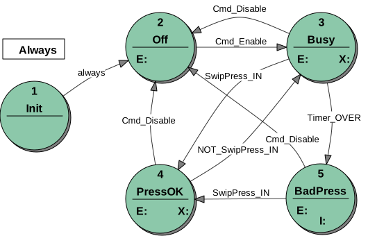
Note that, similar to the Flow state machine, we added a Do output which is irrelevant for the control but is used to switch on a lamp in SWLab to show that the gas pressure is ok.
For details of the Press state machine, look at its specification, where the state transition tables contain the details.
Gas Control
Section titled “Gas Control”The Gas state machine has four slaves: one Press and three Flow state machines. The slaves get commands from their Master — the Gas state machine. The Gas state machine uses the states of its slaves to supervise their activity.
The Gas state machine receives its command through a CMD input, MyCmd, exactly like Flow and Press do. Sending the value 2 sets the input name MyCmd_On; sending 1 sets MyCmd_Off.
Considering their behavior, the three Flow state machines are the same. Therefore, we have only one type of Flow state machine in the system. The three Flow state machines controlled by the Gas state machine are three instances of the same state machine. The differences among the Flow state machines are in their properties, such as timeouts, retries, flow set values, supervised flow limits, etc. These are just set as properties of Flow state machine objects. Note that the Flow machine does not regulate the flow: it merely passes an assigned parameter to the PID controller to fix the set point. This would be exactly the same were the PID controller to be a software package running under the same processor, rather than an external device: the Flow state machine neither knows nor cares about such details.
The state transition diagram below shows that the behavior of the Gas state machine is relatively simple, as the detailed control problems on the device level are handled by the Press and Flow state machines.
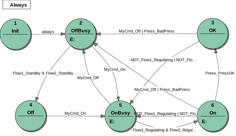
The details of Gas control can be found in its specification, especially in the state transition tables.
Conclusion
Section titled “Conclusion”The Gas control system with its 5 state machines is a typical example of a hierarchical system of state machines. The Master (Gas) and its Slaves (3× Flow and Press) communicate using a command–state interface: the Master sends commands and supervises the reaction of the Slaves to its commands by monitoring their states.
The case study also illustrates how such a system deals with numerical data. Although we have taken pains to point out that real data, particularly numerical data, is kept out of the state machine specifications generated when designing with StateWORKS, the control system does, of course, need to handle such data, such as pressure and flow settings.
After installing StateWORKS Studio, you can find the Gas project in the Samples directory of the Project folder. Several variants are available; the discussion in this case study applies to the Gas3 project. You can examine the state machines and system specifications, and run it using SWLab and SWMon. Alternatively, you can inspect the automatically generated specification details.
If you set in SWMon Gas:MyCmd to 2 (On), the Gas state machine goes to the OnBusy state and sends the command Regulate to all Flow state machines. The input values of the measurement instruments are simulated by Ni, and must be set in SWLab. The correct, expected values are:
Press:Ni:ActualPressureValuein the range 5–7FlowN:Ni:ActualFlowValuein the range 200–240
You can confirm the values by checking the matching SWIP object in SWMon (Press:Swip:Pressure, FlowN:Swip:FlowRange) — its Control Value should read IN. Once all three Flow machines reach Regulating and Press reaches PressOK, Gas advances through On to OK.
The values result from the (arbitrarily chosen) properties (scale factor, etc.) for these elements. The values and properties for all Flow objects are the same.
Do lamps signal whether the set values (states) are achieved. The No output for each Flow valve is driven by that Flow’s Par:FlowSetValue parameter, which starts at an initial value of 500 (adjustable between 300 and 700).