
Microwave Oven Control
The control of a microwave oven is relatively simple and does not present any challenge to the designer. We have chosen it to show the usage of real-time-database (RTDB) objects. The RTDB objects are of various types and may realize some control functions. A correct use of these functions simplifies the state machines. Some obvious examples of control functions are counters which count commands, events, clock pulses (timers), etc. In this example, we want to show the usage of switch points (SWIP), which in RTDB-based systems are used to supervise whether an object value stays within limits.
The requirements are: The oven has a Run push button to start (apply the power) and a Timer that determines the cooking length. Cooking can be interrupted at any time by opening the oven Door. After closing the Door, cooking is continued. Cooking is terminated when the Timer elapses. When the Door is open, a Lamp inside the oven is switched on; when the Door is closed, the Lamp is off.
The control system has the following inputs:
- Run push button - when activated, starts cooking,
- Timer - while this runs, keep on cooking,
- Door sensor - can be true (door closed) or false (door open).
And the following outputs:
- Power - can be true (power on) or false (power off),
- Lamp - can be true (lamp on) or false (lamp off).
The knobs to set the power and timeout values are irrelevant for the control state machine. The behavior of the microwave oven control is determined by the Run push button, Timer, and Door sensor.
First simple solution
Section titled “First simple solution”The first approach is simple, and we consider only the basic requirements as written down previously. We will later analyze the missing control function and specify a more complete control system. For now we have this state transition diagram:
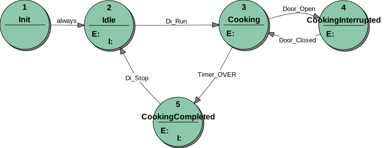
The details of the state transition diagram are in the state transition tables of each state. To view them, you need to use StateWORKS Studio or take a look at the specification details.
This simple solution has some weak points. Of course, microwave ovens are manufactured in different flavors with slightly different controls. Thus, we cannot analyze all possible variants we see on the market. For the purpose of our exercise, we will consider the timer. The timer usage is not perfect, namely, the control system always starts, even if the timeout value is set to 0. To reset the system for the next start, we have to open and then close the door: if you do not like this, then you will find the exercise of changing the design very educational.
More realistic control
Section titled “More realistic control”To achieve a more elaborate control, we not only make sure that the door is closed before cooking starts, but introduce a condition Swip_TimeoutNotZero which, together with Di_Run plus Door_Closed (using a logical AND operation), forms the condition for the transition from the state Idle to Cooking. (For the purposes of this study we show here only the transition table for the Idle state.)
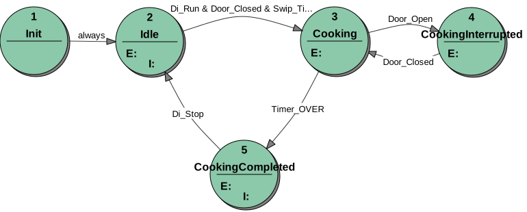
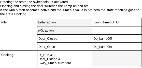
A Switch-point in the RTDB is a mechanism for testing any numeric value and producing a set of Control Values in the positive-logic convention employed by StateWORKS to govern possible transitions. Instead of using the Control Values directly, we use control names (see the more detailed explanation later in the “RTDB objects” section). Commonly, we employ names such as In_Permitted_Range, Too_High, and Too_Low. Here, we only need to use the one “name”, Swip_TimeoutNotZero.
The specification is abstract, so we do not care at this moment how we might get the conditions. At this moment, the VFSM specification defines a link to the real object in the RTDB by choosing the needed object types and using their control values to define control names, such as Swip_TimeoutNotZero.
Later, during the detailed system configuration, we can decide which specific timer will be used for oven control and link its timeout value with a parameter (set by a timer knob on the microwave oven front panel). That parameter, in turn, will be an object to be supervised by a switch point. We may show the dependencies specified in the RTDB by the following diagram:

RTDB objects
Section titled “RTDB objects”The RTDB consists of objects. Objects are of different types, i.e., they have different properties; specifically, they have different Values and Control Values.
A parameter object may have a Value of type integer, float, string, etc. It may also have a Control Value, but we do not discuss it here as it is irrelevant to the example. In our example, the Parameter stores the timeout value, which is an integer representing the number of seconds.
The timer object value is its counter output, which represents the elapsed time from the timer start. It continuously compares the counter output with the timeout value (in this case, supplied by the Parameter object) and defines the timer Control Value. If the timer has not been started yet, the Control Value is RESET. If the timer runs (the counter counts some time pulses), the Control Value is RUN. If the counter output equals the timeout value, the Control Value is OVER.
A switchpoint object (SWIP) compares some object Value with its Values, which represent, in this case, Low and High levels according to the following diagram:

In our example, the Switchpoint object compares its values (1 and a very large number) with the Parameter value, which is a timeout. The result of this comparison is the Switchpoint Control Value, which may be LOW, IN, or HIGH. As we are interested only in the value 0 of the Parameter, we use the Control Value IN as a condition name, Swip_TimeoutNotZero. Note that the IN range includes the two limit values.
Yet another change
Section titled “Yet another change”To demonstrate the flexibility of RTDB, we will show you how to change the timeout value if it is determined by a potentiometer. The potentiometer delivers an analog signal — a voltage. So, we use a Numerical Input (NI) object in the RTDB to store the voltage and use this object as a source of Const value for the Timer object and as an Input for the Switchpoint object. In other words, the only change is to replace the Parameter with the Numeric Input.
Conclusions
Section titled “Conclusions”A state machine determines the behavior of a control system. The complexity of the state machine depends, among other factors, on the means which are to be used to build the control system: the input/output system (hardware interface) and the system resources (timers, counters, etc.).
The RTDB provides a set of already-prepared objects which can simplify the design of a control system by implementing some general control functions. In this article, we have shown one of these control functions: supervision of a certain value.
You may have noticed that the requirements as specified in the beginning were not very detailed. We did that on purpose, as it is often the situation with which we are confronted in a real project. Not until we see the first solution do we “discover” that it is not what we expected. Well, formally, the first simple solution fulfilled the requirements. To start a project with an incomplete specification is not desirable, but it is a common practice and often unavoidable. Anyway, eventually, we completed the revision of the requirements, and the second solution seems to be more realistic.
A real project may require additional control functions. A microwave oven usually has a rotating platform which turns when the power is applied: separate controls for the power and the motor may be required. There are microwave ovens which “store” the Start signal even when the timeout is 0: in such a case, we may first push the Start button and later, at any time, start cooking by setting the timer. Another problem may be the setting of the timeout value: it may be a direct digital signal, an input from a keyboard, or an analog setting adjusted by a potentiometer: these possibilities require different solutions in the RTDB. However, the details may vary; any requirements can be transformed into a neat VFSM specification implemented by means of the StateWORKS system.
We have used such simple examples to illustrate some important aspects of StateWORKS, particularly the use of RTDB objects. You can experiment with this example using the Laboratory Simulator (SWLab), a simulation tool that supports the development of control systems and is available for download. Using StateWORKS Studio, you can change the behavior of the MWOven control and test it in SWLab, which simulates inputs and outputs and contains the VFSM executor. To understand what is happening, do not merely open the state machine and its states; also explore the “Dictionary” and “Name” pull-down menus in the top toolbar, as well as the open “Project” window, to see how the various objects are defined and configured.
Check out the specification details automatically generated by StateWORKS or install the IDE to inspect and test the system. When testing, start SWLab and open the MWOven.swd file. It then displays the DI inputs: Door and Run, the DO outputs: Power and Lamp, and the NI input: CookingTime. As CookingTime is initialized to 2048, you would probably like to set it to some lower value or 0 in the beginning. (Take no account of the scale markings, which are only intended as a logo for a numeric setting. You can quickly alter the setting by moving the pointer with a mouse select/move operation.) Alternatively, you may set the Offset property of MW:Ni:CookingTime when specifying the RTDB to -2048.