
Traffic Light
We received an email where the author stated that he had recently read A. Holmberg’s paper, Designing a State Machine to Solve a Problem ↗ (pp. 34–36), and that it had discouraged him from using this concept. The paper explains how to design a control system using a UML statechart technique. To show the “easiness” of that approach, a really trivial textbook example of a traffic light at an intersection of two roads is discussed. To solve this simple control problem, the reader is confronted with a series of contradictory views:
- States having the same effect (for instance, “both lights red”) could be treated as a single state; the presented solution then uses duplicate states to make the transition simple!
- There are events, special events, and signals; all of them can trigger a transition, but in different ways!
- Hardware and software state machines are different concepts!
- Half of the paper is devoted to an amusing discussion of how to solve the problem of a “minimum green interval on the highway”. To solve this alleged difficulty, the UML semantics require the concept of hierarchy (in other words, embedding a state machine in a state), positive state condition or positive synchronization on the transition, recording events (vehicle detected) during the Highway green state, and setting a flag on entering the state. This heavy and, frankly speaking, completely incomprehensible discussion ends with a statement that there are other ways to deal with this problem, but their UML syntax is too complex to be discussed in the paper!
- At the end, the paper indicates that an alternative way of solving the problem would be to model the state machines as two parallel regions in the same top-level state machine!
- The reader did not reach the end, giving up at the hierarchical state. As a result, he missed the final statement, “in general it is a good thing to keep things as simple as possible”, followed by a remark about the merits of a graphical tool that supports this really neat way of raising the abstraction level…!
The author of the email wrote that his problem contains tens of events and actions that, by his estimates, require probably 20 or so closely cooperating state machines. If the solution of a trivial problem is as complex as presented in this paper, he does not see any chance of solving any real problem using state machines.
Last but not least, the paper does not even show a complete solution for the traffic light controller. It is obviously too complex for UML notation to fit in a paper.
We sent an answer to this email suggesting that the author avoid UML altogether. A state machine is an excellent concept for modeling control problems, especially complex problems. But UML is the last thing that he should be considering as a potential development tool for complex control problems with state machines. We are not aware of any truly complex control applications having been implemented using UML.
What a Rigorous State Machine Model Requires
Section titled “What a Rigorous State Machine Model Requires”A rigorous understanding of state machine concepts implies:
- That the user understands what a state is.
- A state machine is triggered by events, but the transition and input action conditions are logical expressions of actual inputs.
- State machine concepts are the same for hardware and software. A state machine is an abstract model of behavior.
- The idea of state hierarchy in a UML statechart is nothing but the replacement of several states by a pseudo-state. It is an interesting idea but unsuitable for any complex system which requires a genuinely hierarchical system of state machines.
- The concept of concurrent state machines is an interesting idea, but there are no convincing arguments that a system of state machines needs concurrency, especially a trivial one. Parallel systems are difficult to design, debug, and supervise and should be used only if they are essential. Creating threads and exchanging messages among them might be interesting for programmers, but it does not mean that we need these in all situations.
A Simple Traffic Light Controller
Section titled “A Simple Traffic Light Controller”To make our observations more clear, we show the solution of this trivial example from the paper. It looks as follows:
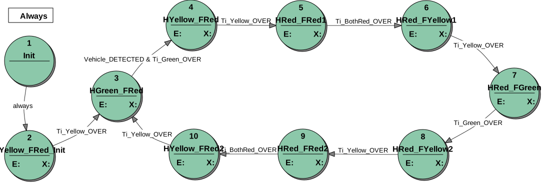
A standard traffic light controller switches periodically through a red-yellow-green-yellow sequence of lights for both roads, thus ensuring collision-free traffic. Depending on the intersection complexity (pedestrian push buttons, sensors detecting the traffic intensity, overlapping red lights for both roads, etc.), the basic light switching algorithm may have additional requirements. In addition, it may require some supervision dictated by the controlled hardware (for instance, a delay on start-up). In the discussed example, the requirements are: if there are vehicles on the Farm road, this intersection has a standard fixed-time traffic lights sequence (after a minimum time period between such sequences); otherwise, the Highway gets the green light all the time. The presence of vehicles on the Farm road is detected by a sensor that is active if at least one vehicle is present in the supervised zone.
The standard traffic light state machine consists of a sequence of states, each switching off or on some lights. In addition, on entering a state, the state machine starts a corresponding timer. If the running timer elapses, the timeout event causes a transition to the next state.
Adding the Farm Road Sensor Requirement
Section titled “Adding the Farm Road Sensor Requirement”The traffic light controller in the paper deviates from the usual, purely timed controller by a requirement that if there are no vehicles on the Farm road, the periodical change of lights should be disabled and the Highway should have a constant green light. That requires a change of the transition from a state HGreen_FRed to the state HYellow_FRed, which for the usual solution reads: Ti_Green_OVER. Changing it to Vehicle_DETECTED & Ti_Green_OVER will do. If the vehicle is not detected, the Vehicle_DETECTED condition being unset blocks the timed transition. If both conditions are true: Vehicle_DETECTED is set and the timer for the green light elapses, the state machine starts a new standard traffic light cycle. We added an Init state to the state transition diagram that assures a safe start-up of the traffic light system: the Highway gets the yellow light and the Farm road gets immediately the red light.
Check out the specification details automatically generated by StateWORKS. Of course, this is the complete solution: it requires no coding and can be executed directly.