
Lifetime of Control Signals and Generating Events
Lifetime of control signals and the generation of events, illustrated by a Turing machine ↗.
Introduction
Section titled “Introduction”A control system reacts to input signals that change over time. The period between two consecutive changes of a signal is defined as its lifetime. Depending on the type of signal, it may be desirable to shorten its lifetime by “consuming” it before the next change occurs.
In most software control systems, a change in a signal value generates an event that triggers its processing. In such systems, repeating the same value usually does not make sense, but it may nevertheless be required. A similar problem exists for outputs that should be “detected” by the outside world when they change.
The lifetime of control values and the generation of input and output events are the topics of this technical note. The discussion is supported by an example of a state machine controlling a Turing machine model.
Consuming Control Values
Section titled “Consuming Control Values”The behavior of a state machine in a given state depends on its inputs. In the VFSM approach, the virtual inputs represent the entire input information in the form of control values. A control value is entered into a virtual input when the corresponding real input changes. Control values have different characteristics.
Any input is characterized by a set of control values that are, as a rule, mutually exclusive. At least, this is the philosophy followed by the RTDB. For instance, a digital input (the DI object in the RTDB) has three control values:
LOW(representing e.g.DoorOpen)HIGH(representing e.g.DoorClosed)UNKNOWN(representing e.g.DoorPositionUnknown)
The virtual input always contains one of these values. Any value can be replaced by another value from the same set, but this happens only when the real input changes. We may say that the lifetime of such a control value is determined by the duration of the corresponding real input value.
Another input type represents a command (the CMD object in the RTDB) and has several control values corresponding to numeric command identifiers. For example:
- 1 (representing e.g.
CmdStart) - 2 (representing e.g.
CmdStop) - 3 (representing e.g.
CmdContinue) - 4 (representing e.g.
CmdStep)
The virtual input may contain one of these values. Any value can be replaced by another value from the same set when the command changes. In addition, a command control value may be explicitly removed from the virtual input by using the output action MyCmd_Clear. Technically, the command is assigned a null value to clear it. This situation means that the last command has lost its meaning, but no new command has been issued yet.
An extreme type represents inputs whose control values are consumed — removed or replaced by another value — once they have been used. Strings in parsers are examples of such inputs. In the RTDB:
- The
PARobject changes fromCHANGEDtoDEFwhen it is used. - The
STRobject becomes effectively disabled in theMATCHandNOMATCHstates and must be enabled by forcing a change to theSETstate.
Another example is the XDA object, which is often used — and sometimes misused — for inputs whose values are consumed. Therefore, we shall discuss its use in more detail.
The XDA object is similar to a CMD object but without its restrictions, such as being limited to the Master–Slave interface. The XDA object is an unsigned integer and may be used to represent:
- input signals;
- output signals.
This explains its usefulness when a designer must decide on the lifetime of control signals represented by XDA values.
Consuming an XDA control value means defining an output action that sets it to a neutral value that is not used to create another control value. For instance, in the example below, we use MoveDone (1) as a control value. Using an action such as ClearMoveDone to set the XDA value to 0 effectively removes the XDA control value from the virtual input.
Generating Input Events
Section titled “Generating Input Events”The VFSM executor is triggered by events. An event is caused by a change in a control value. For some objects, the possible changes are obvious. For example, a digital input may change as follows: LOW → HIGH, LOW → UNKNOWN, HIGH → LOW etc.; Such a change does not make sense: LOW → LOW
The problem is less obvious for certain other objects that behave like commands. In addition to changes such as CmdStart → CmdStop, we may want to repeat the same command. Repeating a command means, for example, applying CmdStep several times in succession.
Unfortunately, receiving the same command value again does not represent a change for the command object. In such situations, we must force an intermediate dummy change, thereby regenerating the object’s ability to create an event. For the CMD object, a special Clear action is available.
Another object often used for this purpose is XDA. It is an input/output object and, when used as an input object, it also requires a dummy value to be used as an action. This dummy value serves as a “break” between two identical input values.
Output Action Events
Section titled “Output Action Events”A different lifetime problem exists for outputs defined by objects used to define actions. Performing an action means triggering an I/O handler that passes a real value to the controlled application. The action can be repeated at any time.
When TCP/IP communication is used for this purpose, clients are advised only when an object value has changed. Performing the same action means setting the same value, which does not generate an event to be sent to the clients. Consequently, outputs controlled through a TCP/IP link cannot repeat the same value.
Of course, if the value represents a digital output, there is usually no reason to repeat it. However, if the output has a “command” character — meaning “do something” — we may want to repeat an action, such as commanding several movements in the same direction.
Such an application requires two identical actions to be interleaved with dummy actions (“do nothing”), which effectively produces the required events.
As already mentioned, string processing is an extreme example of events that, as a rule, must be consumed immediately after they are used. Therefore, we have chosen a Turing machine as an example to support our discussion.
In this example, we can demonstrate all the problems discussed above:
- consumption of used input control values;
- regeneration of the event-generation ability of input objects;
- generation of output events for repeated actions.
The reader may download the example and study it using StateWORKS Studio.
Turing Machine
Section titled “Turing Machine”A Turing machine consists of a tape and a read/write head. The head can move along the tape, or the tape can move relative to the head, to the right or left. The head can read a symbol from the tape and write a symbol onto the tape.
The operation of a Turing machine is determined by a finite state machine that reacts to the symbols scanned by the head. After each movement, the head reads a symbol from the tape. Depending on the symbol read, the finite state machine decides what to do:
- leave the symbol on the tape or overwrite it with another symbol;
- move to the right or to the left.
A Turing machine does not have much practical meaning, but it is a useful conceptual model for studying automata.
Turing Machine Model
Section titled “Turing Machine Model”We have prepared a model of a Turing machine. The actual model consists of a tape represented by 24 cells, each of which can contain the digit 0 or 1. The position of the head is indicated by a cell with a red border.
By running an appropriate state machine, we can solve a specific problem using the Turing machine. The state machine controls the movement of the head and the writing of symbols onto the tape.


The full graphical user interface of the model, which was written in C++ Qt Widgets (6.12), is shown below. The model connects to the RTDB-based StateWORKS runtime system, for example SWLab, which runs a state machine that controls the Turing machine.
The upper part of the window displays information about the connection. A log of all signals received by the Turing machine is shown in the lower part of the window. Note that the list reads from left to right.
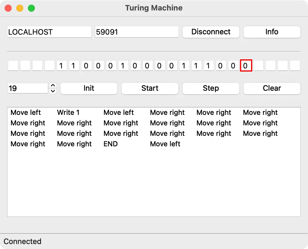
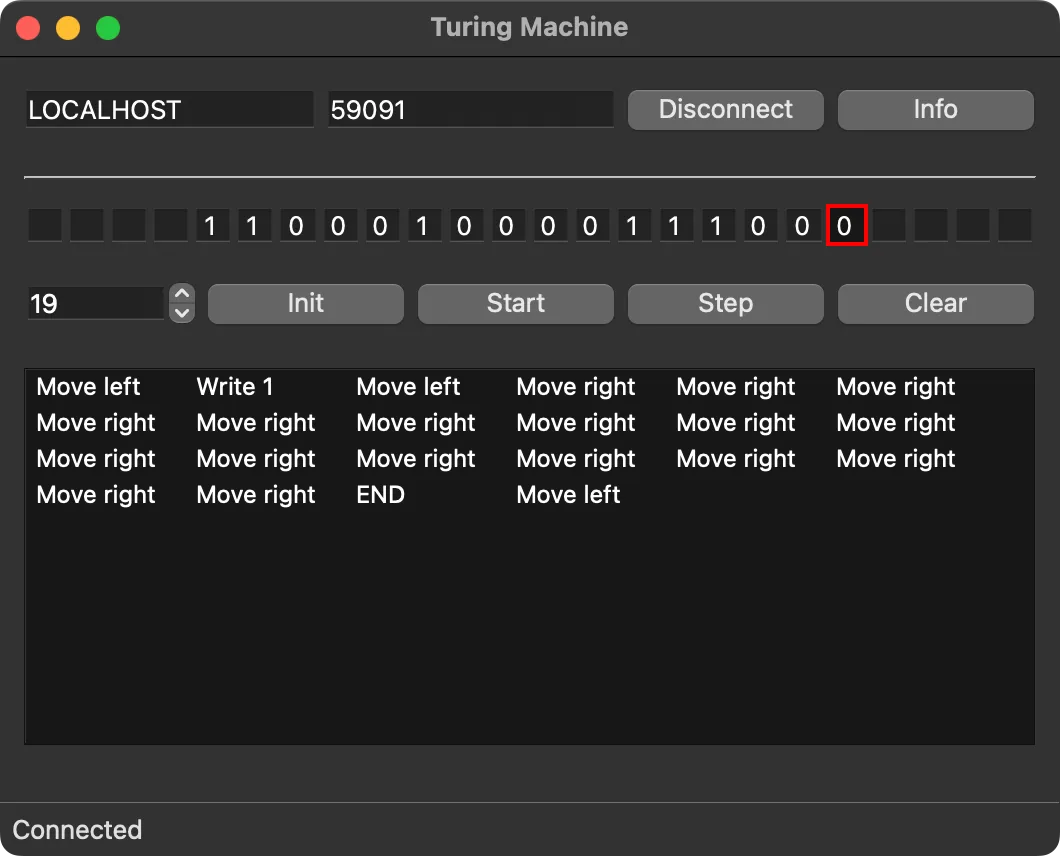
The model uses advise on the XDA objects Move and Write through their .Val attributes. Consequently, any change to these values triggers the Turing machine.
The machine can perform two operations:
Write:0,1,2(clear the cell content), and4(end the operation).Move:0(move left) and1(move right).
The Write operation is acknowledged by a WriteDone signal with the value 1:

The Move operation is acknowledged by a MoveDone signal with the value 1. In addition, the current input symbol under the head is read and sent to the RTDB, where the value of the Input object is set:

The Input symbols are limited to:
0and1, corresponding to the0and1Writesymbols;- any other unsigned integer, which is interpreted as an empty cell. In the examples, the value
2is used for this purpose.
In addition, the value 3 is used in the state machine specification for both Input and Write to denote a “none” symbol.
The Turing machine model has the following buttons:
- Connect / Disconnect: Connects to or disconnects from the StateWORKS runtime system via TCP/IP.
- Info: Displays the configuration path and a list of the RTDB objects used.
- Init: Initializes the cells with a predefined string defined by the objects
Par:InitString,Par:Begin,StringPos, andPar:StartPos. The string length is limited to 24 characters. The string and the starting position can also be entered manually. - Start / Stop: Starts or stops processing of the tape.
- Step: Performs one processing step.
- Clear: Clears the contents of the log.
Analysis of the Example
Section titled “Analysis of the Example”Any Turing machine using the binary alphabet can be realized and studied using the software model.
We have prepared an example that calculates the two’s complement of a binary number using the well-known algorithm:
- Check the digits from the rightmost position, leaving them unchanged until a
1is encountered. - Leave the first
1encountered unchanged. - Continue checking to the left while inverting all subsequent digits.
The initialization values are:
| Object | Value |
|---|---|
Par:InitString1 | 0100010000111000 |
Par:BeginStringPos | 4 |
Par:StartPos | 19 |
This is the state transition diagram of the state machine that controls the Turing machine and performs the conversion:
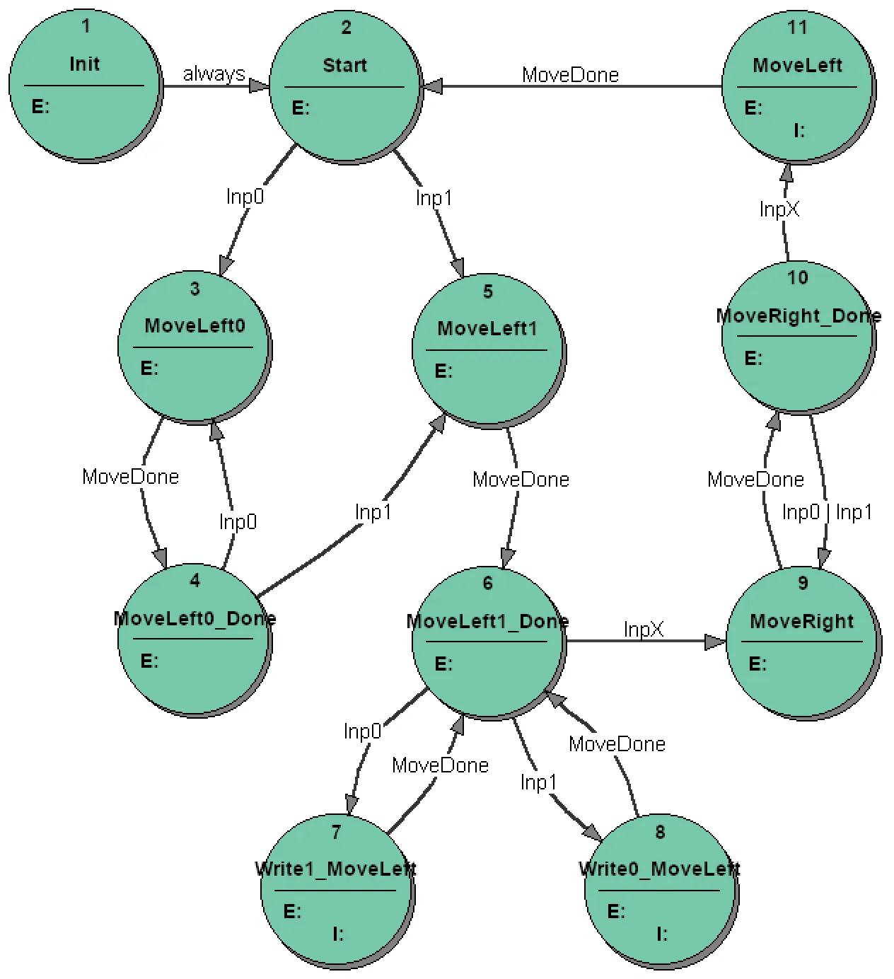
The processing of the binary number has three phases:
- Moving to the left until the digit
1is encountered — realized by the statesMoveLeft0andMoveLeft0_Done. - Skipping the first digit
1and negating all following digits — realized by the statesMoveLeft1,Write1_MoveLeft, andWrite0_MoveLeft. - Terminating the processing when an empty cell is encountered and returning the head to the initial (left) position — realized by the states
MoveRightandMoveRight_Done. The initial position is identified when the head detects an empty cell, which causes the last movement to the left in the stateMoveLeft.
The details of the solution can be studied in the project T_TwoComplement or by looking at the specification details. By running the application, for example using SWLab, we can test it more carefully by changing the binary number and running the conversion continuously using the Start/Stop button or step by step using the Step button.
The log shows all Move and Write commands sent to the Turing machine model.
We will limit the discussion to an analysis of the states that demonstrate solutions to the problems discussed at the beginning: consumption of control values and generation of input and output events.
We consider the two states MoveLeft0 and MoveLeft0_Done:
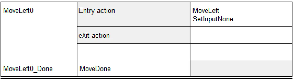
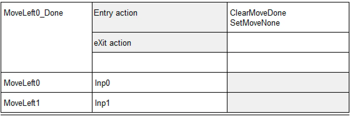
On entering the state MoveLeft0, the state machine issues the output MoveLeft and waits for an acknowledgement. Upon receiving the MoveDone acknowledgement, the state machine transitions to the state MoveLeft0_Done, where it clears the MoveDone control value.
In both states, dummy actions are performed to allow objects to generate events:
- The action
SetMoveNonein the stateMoveLeft0_Doneallows theMoveLeftaction to be repeated after returning to the stateMoveLeft0. - The action
SetInputNonein the stateMoveLeft0ensures an input event in the stateMoveLeft0_Done.
The state machine sends either a Move signal or both Move and Write signals to the Turing machine. In the latter case, the sequence Move → Write must be guaranteed.
Instead of using two states, we have arranged the sequence as shown in the state Write1_MoveLeft:
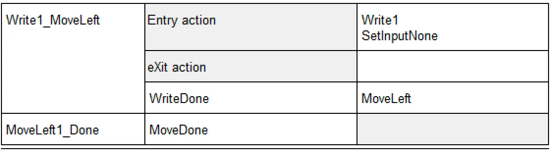
On entering the state Write1_MoveLeft, the state machine sends the Write1 signal to the Turing machine. Upon receiving the WriteDone acknowledgement, the state machine sends the MoveLeft signal as an input action.
If this signal is acknowledged by the MoveDone signal, the state machine transitions to the state MoveLeft1_Done.
Conclusions
Section titled “Conclusions”When coding a parser-type application, we use events to trigger a function that processes the corresponding string or message. When executing the specification directly with the help of the StateWORKS runtime system, we must explicitly handle the consumption of events and the regeneration of the ability to create events.
Although parser-type problems are relatively rare in some environments, such as industrial control, the RTDB allows us to handle them efficiently.
The model of a Turing machine created for this note may be used to study Turing machine exercises defined for a binary alphabet . By specifying an appropriate state machine, we can solve and test any problem within that range.
Footnotes
Section titled “Footnotes”-
Defines the 16-bit binary number to be converted into its two’s complement. ↩